Coordinate Frames
In this manual, coordinate frame systems are simply referred to as frames. This page is to assist the developer in choosing and implementing the appropriate coordinate frames for their respective application. It should be noted that the following frames are in relation to the IMX itself.
Coordinate Frame Relationship
The relationship between the Hardware Frame, Sensor Frame, and INS Output Frame are as follows.

NOTE: The Hardware Frame and Sensor Frame are equivalent when the sensor rotation in DID_FLASH_CONFIG.sensorConfig is zero. The Sensor Frame and INS output Frame are equivalent when the DID_FLASH_CONFIG.insRotation and DID_FLASH_CONFIG.insOffset are zero.
Hardware Frame
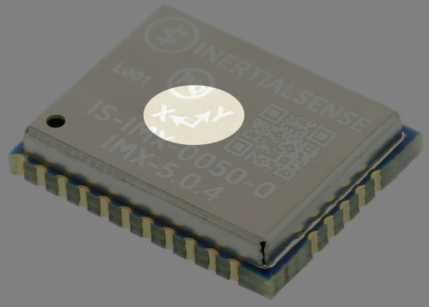
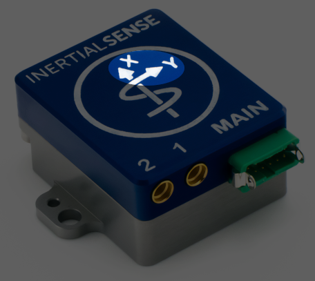
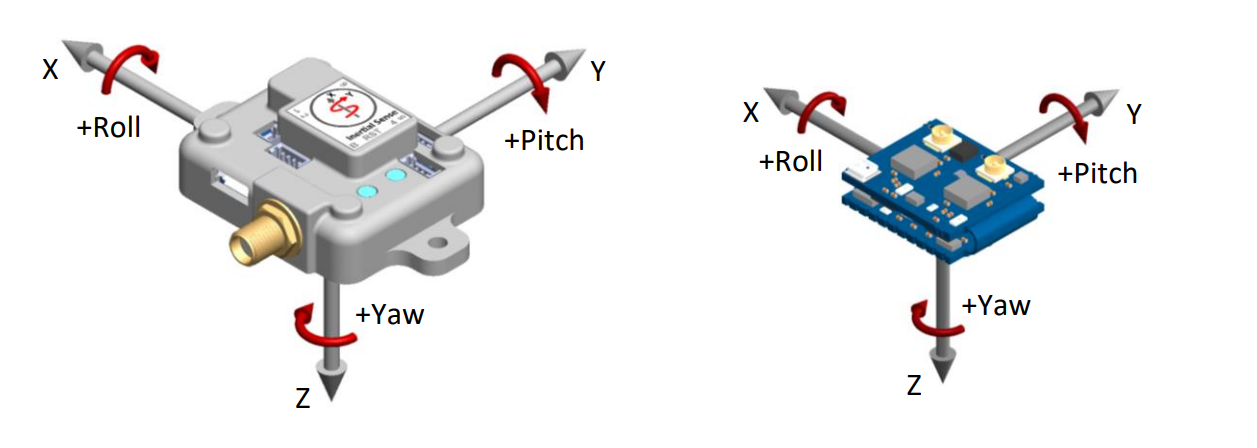
The Hardware Frame is labeled "X" and "Y" on the hardware indicating the direction of the sensing elements in the IMX.
The IMX follows the right-hand rule for XYZ axis relative direction and angular rotation.
Sensor Frame
The IMU and magnetometer data (i.e. messages DID_IMU and DID_MAGNETOMETER) are in the Sensor Frame. The Hardware Frame is rotated into the Sensor Frame in multiples of 90° using the SENSOR_CFG_SENSOR_ROTATION_MASK bits of the DID_FLASH_CONFIG.sensorConfig as defined in enum eSensorConfig.
INS Output Frame
The INS output data (DID_INS_1, DID_INS_2, DID_INS_3) is in the INS Output Frame. Translation from Sensor Frame to INS Output Frame is defined as:
- Sensor Frame → Intermediate Output Frame by rotation of
DID_FLASH_CONFIG.insRotationeuler angles (in order of heading, pitch, roll angle) In radians. - Intermediate Output Frame → INS Output Frame: Offset by
DID_FLASH_CONFIG.insOffsetin meters.
If DID_FLASH_CONFIG.insRotation and DID_FLASH_CONFIG.insOffset are zero, the Sensor Frame and the INS Output Frame are the same.
North-East-Down (NED) Frame
Position estimates can be output in the North-East-Down (NED) coordinate frame defined as follows:
* Right-handed, Cartesian, non-inertial, geodetic frame with origin located at the surface of Earth (WGS84 ellipsoid). * Positive X-axis points towards North, tangent to WGS84 ellipsoid. * Positive Y-axis points towards East, tangent to WGS84 ellipsoid. * Positive Z-axis points down into the ground completing the right-handed system.
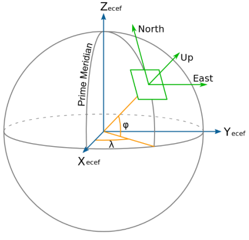
Earth-Centered Earth-Fixed (ECEF) Frame
The Earth-Centered Earth-Fixed (ECEF) frame is defined as follows:
* Right-handed, Cartesian, non-inertial frame with origin located at the center of Earth. * Fixed to and rotates with Earth. * Positive X-axis aligns with the WGS84 X-axis, which aligns with the International Earth Rotation and Reference Systems Service (IERS) Prime Meridian. * Positive Z-axis aligns with the WGS84 Z-axis, which aligns with the IERS Reference Pole (IRP) that points towards the North Pole. * Positive Y-axis aligns with the WGS84 Y-axis, completing the right-handed system.
Coordinate Frames Transformation Functions
This section is intended to be an example of how to rotate between frames using utility functions defined in the InertialSenseSDK.
Body frame to NED frame
The following example converts body velocity DID_INS_2.uvw to NED velocity vel_ned.
#include "SDK/src/ISPose.h"
quatRot( vel_ned, DID_INS_2.qn2b, DID_INS_2.uvw );
The following computes ground track heading based on DID_INS_2.uvw body velocity in the local tangent plane.
#include "SDK/src/ISPose.h"
quatRot( vel_ned, DID_INS_2.qn2b, DID_INS_2.uvw );
ground_track_heading = atan2f( vel_ned[1], vel_ned[0] );
This following example removes gravity from the IMU measured acceleration.
#include "SDK/src/ISPose.h"
Vector gravityNED = { 0, 0, -9.80665 }; // m/s^2
Vector gravityBody;
Vector accMinusGravity;
// Rotate gravity into body frame
quatConjRot( gravityBody, DID_INS_2.qn2b, gravityNED );
// Subtract gravity from IMU acceleration output
sub_Vec3_Vec3( accMinusGravity, DID_IMU.I[0].acc, gravityBody );
ECEF frame to NED frame
This example converts ECEF velocity vel_ecef to NED velocity vel_ned.
#include "SDK/src/ISPose.h"
quat_ecef2ned( lla[0], lla[1], qe2n );
quatConj( qn2e, qe2n );
quatRot( vel_ned, qn2e, vel_ecef );