Basic Arduino Communications Example Project
Interfacing with the IMX over serial
This example shows how to communicate with the IMX using the Inertial Sense Binary Communications Protocol. The example code can be found in the Inertial Sense SDK/ExampleProjects/Arduino.
Important
Update the IMX to the latest firmware
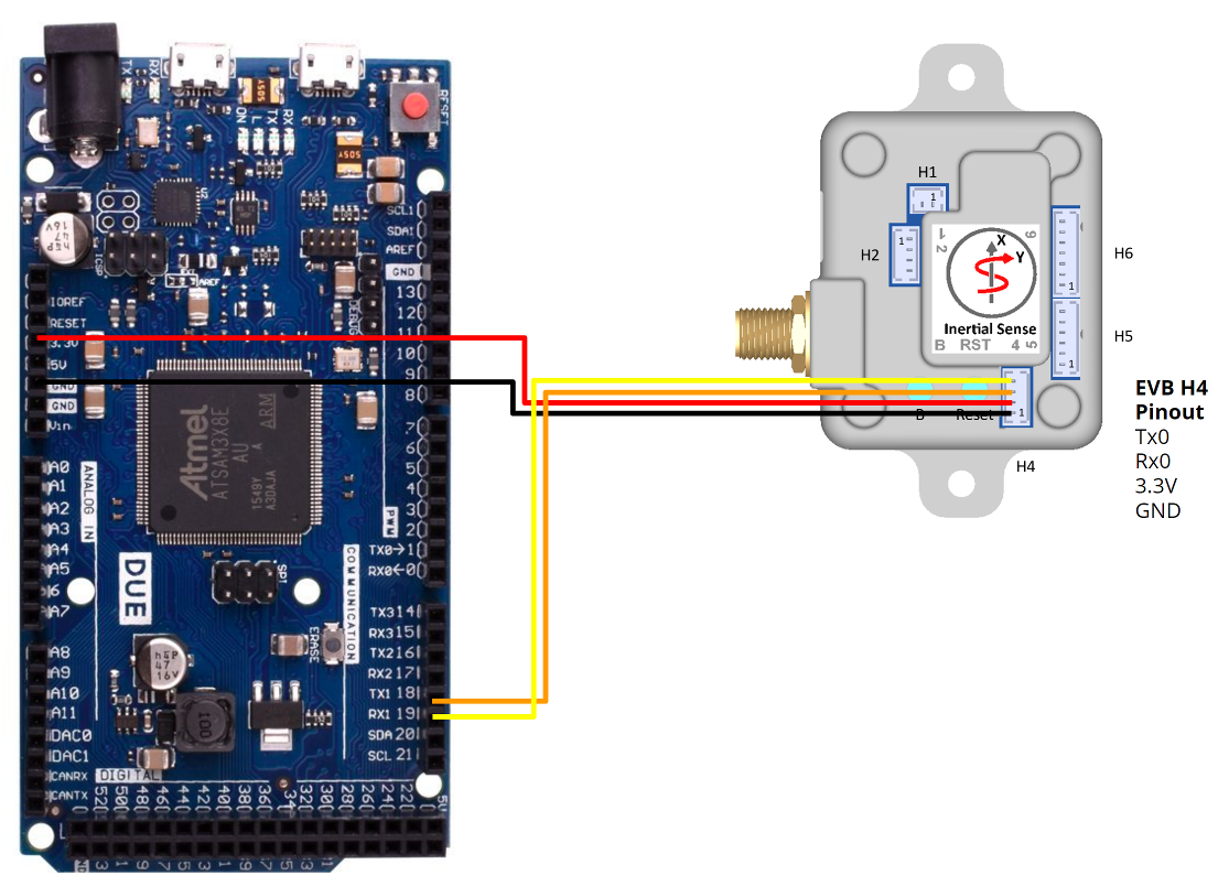
This example demonstrates how to use the Inertial Sense EVB with an Arduino Due. The Due was selected because it has two serial ports. This way the Arduino can communicate with the IMX using one of the ports, and write the output over the Serial Monitor to the computer using the other.
Warning
The InertialSense SDK requires 64-bit double support. 32-bit processors (Arduino Due, Zero, and M0) are supported. 8-bit processors (i.e. Arduino Mega and Uno) are NOT supported. The ASCII protocol (not covered in this example) may be used on an 8-bit Arduino.
Note
A Raspberry PI (similar in price to the Arduino) is a good alternative to the Arduino. Either the Binary Communications and ASCII Communications example projects can be run on a Raspberry PI.
Wiring Guide
After downloading the Inertial Sense SDK, Navigate to ExampleProjects/Arduino/ReadIS. Use the ImportSdkFiles.bat (Windows) or ImportSdkFiles.sh (Linux) to copy the required files from the SDK into src/ISsdk directory. The resulting file structure for the ReadIS Arduino sketch should look like the following:
|-ReadIS
  | - ImportSdkFiles.bat
  | - ImportSdkFiles.sh
  | - ReadIS.ino
  | - src
    | - ISsdk
      | - data_sets.c
      | - data_sets.h
      | - ISComm.c
      | - ISComm.h
      | - ISConstants.h
What is an ino file?
An .ino file is the arduino extension for a sketch. It is actually C++ code.
Note
Note that there are two .c files in the tree. You'll need to make sure that these files are compiled by the toolchain, otherwise xxxx is not defined errors can occur.
SDK Implementation
ReadIS.ino file explained:
Step 1: Add Includes
The "ISComm.h" header file includes all the other required code. stddef.h file from the standard library is required for the offsetof function.
#include "src/ISsdk/ISComm.h"
#include <stddef.h>
Step 2: Create buffers
Next, define a buffer to hold data. As the IMX sends data, this buffer is used to hold the data until a full message arrives. This buffer only needs to be as big as the largest message expected, multiplied by two + 32 (worst case scenario if there is a bad transmission). For this example a 1KB buffer is used.
// This buffer is going to be used to hold messages as they come in.
// You can make this 512 size if memory is tight.
static uint8_t s_buffer[1024];
// create an instance to hold communications state
static is_comm_instance_t comm;
Step 3: Serial Port Initialization
void setup()
{
    // Initialize both serial ports:
    Serial.begin(115200);
    Serial1.begin(115200);

    if (sizeof(double) != 8)
    {
        Serial.println("Inertial Sense SDK requires 64 bit double support");
        while (true)
        {
        };
    }

    Serial.println("initializing");

    // Initialize comm interface - call this before doing any comm functions
    is_comm_init(&comm, s_buffer, sizeof(s_buffer));

    // Stop all the broadcasts on the device
    int messageSize = is_comm_stop_broadcasts_all_ports(&comm);
    Serial1.write(comm.rxBuf.start, messageSize); // Transmit the message to the inertialsense device

    // Ask for ins_1 message 20 times per second.  Ask for the whole thing, so
    // set 0's for the offset and size
    messageSize = is_comm_get_data_to_buf(buffer, bufferSize, &comm, DID_INS_1, sizeof(ins_1_t), 0, 1000);
    Serial1.write(comm.rxBuf.start, messageSize); // Transmit the message to the inertialsense device
}
Initialize the communication using the following steps as shown above:
- Initialize the serial ports
- Tell the communication interface where to find the buffer to use to hold messages, and how big that buffer is.
- Reset communications on the device
- Perform configuration of the IMX
- Tell the IMX what data to stream, and how often
Whenever sending a command to the IMX, the command is put into the buffer, and the length of the message is returned by one of the configuration functions. That buffer needs to be written out to the IMX for the command to be received.
Tip
It is recommended to use the enumerations in data_sets.h such as SYS_CFG_BITS_RTK_ROVER to configure the device. This aids code readability and reduces the chance for errors.
In this example, the DID_INS_1 message is streamed. All available messages can be found in the data_sets.h file, defined as C-style structs.
Step 4: Handle Received Data
void loop()
{
    // Read from port 1, and see if we have a complete inertialsense packet
    if (Serial1.available())
    {
        uint8_t inByte = Serial1.read();
        // This function returns the DID of the message that was just parsed, we can then point the buffer to
        // the right function to handle the message.  We can use a cast to interpret the s_buffer as the
        // kind of message that we received.
        uint32_t message_type = is_comm_parse_byte(&comm, inByte);
        switch (message_type)
        {
        case _PTYPE_INERTIAL_SENSE_DATA:
            switch (comm.dataHdr.id)
            {
            case DID_NULL:
                break;
            case DID_INS_1:
                handleINSMessage((ins_1_t *)(comm.pkt.data.ptr));
                break;
            default:
                Serial.print("Got an unexpected message DID: ");
                Serial.println(message_type, DEC);
            }
        }
    }
}
is_comm_parse function. For each byte received, this function waits for a complete message in the buffer and decodes it. Once a full message is received, it identifies what kind of message is in the buffer so it can be handled correctly. The easiest way to deal with this is to us a case structure as shown above, with separate "callback" functions for each message type.
The INS message handler is just printing the position in lla, velocity and euler angle attitude to the screen. Other parameterizations of position and attitude are available in other DID_INS_x messages.
static void handleINSMessage(ins_1_t *ins)
{
    Serial.print("Lat: ");
    Serial.print((float)ins->lla[0], 6);
    Serial.print("\t");
    Serial.print(", Lon: ");
    Serial.print((float)ins->lla[1], 6);
    Serial.print("\t");
    Serial.print(", Alt: ");
    Serial.print((float)ins->lla[2], 2);
    Serial.print("\t");
    Serial.print(", roll: ");
    Serial.print(ins->theta[0] * C_RAD2DEG_F);
    Serial.print("\t");
    Serial.print(", pitch: ");
    Serial.print(ins->theta[1] * C_RAD2DEG_F);
    Serial.print("\t");
    Serial.print(", yaw: ");
    Serial.print("\t");
    Serial.println(ins->theta[2] * C_RAD2DEG_F);
}