Multi-band GNSS
Advantages
The advent of multi-band GNSS (multiple frequency global navigation satellite systems) improves accuracy by reducing the impact of errors caused by multi-path and atmospheric distortion. When compared to traditional single-band GNSS, dual-band technology provides about a 2x reduction in average position error (circular error probable - CEP). Benefits of multi-band GNSS systems like the uBlox ZED-F9P receiver include:
- Concurrent reception of GPS, GLONASS, Galileo and BeiDou for better coverage.
- Faster convergence time (GPS time to fix).
- More reliable / robust performance.
- ~2x reduction in average position error (CEP).
- Centimeter-level RTK position accuracy.
- Small and energy efficient module.
- Easy integration of RTK for fast time-to-market.
Overview
The IMX (GPS-INS) can be interfaced with external multi-band (multi-frequency) GNSS receiver(s) connected via serial port(s) to improve precision the EKF solution. The supported message protocols are uBlox binary and NMEA. The following are the GPS settings (accessible in the EvalTool GPS Settings tab and IMX DID_FLASH_CONFIG.ioConfig and DID_FLASH_CONFIG.RTKCfgBits):
| Setting | Value |
|---|---|
| GPS Source | Serial port of the GNSS (serial 0 or 1) |
| GPS Type | GNSS model or protocol (ublox M8, ublox F9, or NMEA) |
| GPS RTK | Position for L1 RTK precision positioning Compass for L1 RTK Dual GNSS heading F9 Position for ZED-F9P mult-frequency RTK precision positioning F9 Compass for ZED-F9P multi-frequency Dual GNSS heading |
| GPS1 Timepulse | Source of the GNSS PPS time synchronization, uBlox GPS type only. |
Refer to the Hardware section of this manual for serial port pinout information.
uBlox ZED-F9P GNSS
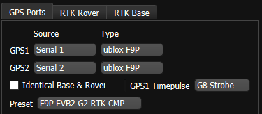
The IMX (GPS-INS) can be configured for use with uBlox ZED-F9P multi-band GNSS receivers. This can be done using either the EvalTool GPS Setting tab or the IMX DID_FLASH_CONFIG.ioConfig and DID_FLASH_CONFIG.RTKCfgBits fields.
| GPS Ports | Value |
|---|---|
| GPS Source | serial 0, serial 1, or serial 2 |
| GPS Type | ublox F9P |
| GPS1 Timepulse | Disable or IMX pin connected to ZED-F9P PPS |
| RTK Rover | Value |
|---|---|
| GPS RTK Mode | F9P Position or F9P Compass |
| RTK Base | Value |
|---|---|
| Serial Port 0 (Single GNSS only) | GPS1 - RTCM3 |
| USB Port | GPS1 - RTCM3 |
The following sections detail how to interface and configure the IMX for operation using the ZED-F9P. See RTK precision positioning and RTK compassing for RTK operation principles.
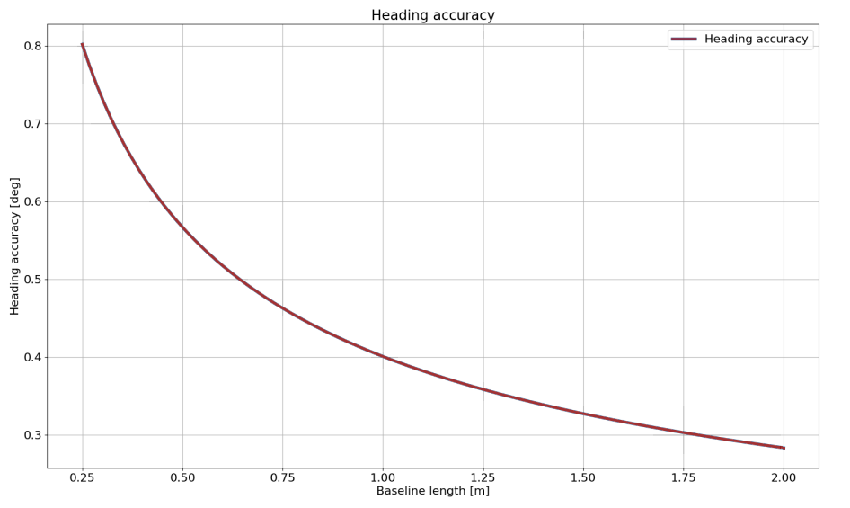
Dual ZED-F9 Heading Accuracy
When using two multi-band ZED-F9 GNSS receivers in moving baseline mode (RTK compassing) such as the EVB-2 Dual ZED-F9, the baseline error is composed of the measurement error plus the RTK solution error. The heading accuracy with ideal conditions is shown in the following plot.
Typical Interface
The IMX will automatically configure the ZED-F9P for communications.
Single GNSS RTK Positioning w/ LiDAR
RTK base messages (RTMC3) supplied to any of the IMX serial ports are forwarded to GPS1 for RTK positioning. The RTK precision position from GPS 1 is used in the IMX EKF solution. The IMX can be configured to output NMEA messages such as GPGGA or GPRMC on any serial port.

Dual GNSS RTK Positioning and RTK Compassing
RTK base messages (RTMC3) supplied to any of the IMX serial ports are forwarded to GPS1 for RTK positioning. RTK moving base messages from GPS1 are forwarded to GPS2 for RTK compassing. The RTK precision position from GPS 1 and the RTK compassing heading from GPS2 are used in the IMX EKF solution. Note that typically the Rugged-2 uses Serial 0 and the EVB-2 uses Serial 2 to communicate with the GPS2 F9P receiver.

Rugged-2
The Rugged-2 INS contains the either single or dual ZED-F9P onboard supporting RTK positioning and compassing. GPS 1 and GPS 2 are connected to serial ports 1 and 0 respectively on the IMX.
Single GNSS Settings
Use the following IMX settings with the Rugged-2-G1 (single GNSS receiver). These settings can be applied either using the EvalTool GPS Settings tab or the IMX DID_FLASH_CONFIG.ioConfig and DID_FLASH_CONFIG.RTKCfgBits fields.
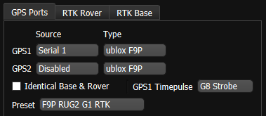
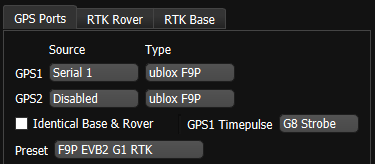
GPS Ports
Set the GPS1 source to Serial 1 and type to ublox F9P.
| DID_FLASH_CONFIG | Value |
|---|---|
| ioConfig (firmware >=1.8.5) | 0x0244a040 |
RTK Rover
Enable RTK rover mode by selecting F9P Precision Position.
| DID_FLASH_CONFIG | Value |
|---|---|
| RTKCfgBits | 0x00000002 |
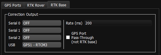
RTK Base
To configuring a system as an RTK base, disable the RTK Rover by setting the GPS1 and GPS2 RTK Mode to OFF, and select the appropriate correction output port on the IMX.
| DID_FLASH_CONFIG | Value |
|---|---|
| RTKCfgBits | 0x00000900 |
Dual GNSS Settings
Use the following IMX settings with the Rugged-2-G2 (dual GNSS receivers). These settings can be applied either using the EvalTool GPS Settings tab or the IMX DID_FLASH_CONFIG.ioConfig and DID_FLASH_CONFIG.RTKCfgBits fields.
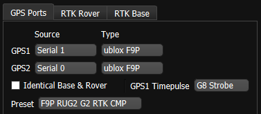
GPS Ports
Set GPS 1 and 2 to source Serial 1 and Serial 0. the serial port that the ZED-F9P is connected to and type to ublox F9P.
| DID_FLASH_CONFIG | Value |
|---|---|
| ioConfig (firmware >=1.8.5) | 0x025ca040 |
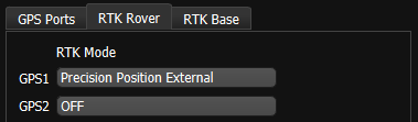
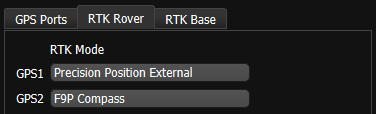
RTK Rover
Enable RTK rover mode by selecting Precision Position External. GPS1 is designated for Precision Position External and GPS2 for F9P Compass settings. Either or both can be enabled at the same time.
| DID_FLASH_CONFIG | Value |
|---|---|
| RTKCfgBits | 0x00000006 |
RTK Base
To configuring a system as an RTK base, skip the RTK rover settings, and select the appropriate correction output port on the IMX. Notice that IMX serial port 0 and 1 may be unavailable and occupied by the dual ZED-F9P receivers.
| DID_FLASH_CONFIG | Value |
|---|---|
| RTKCfgBits | 0x00000900 |
EVB-2 to ZED-F9P
The ZED-F9P can be powered using the EVB-2 +3.3V output. Either serial 0 or serial 1 can be used to communicate with the ZED-F9P. See the EVB-2 H7 pinout for details.
Single GNSS Pinout
| EVB-2 | IMX | ZED-F9P |
|---|---|---|
 H7-1 H7-1 |
GND | GND |
 H7-3 H7-3 |
+3.3V | 3V3 |
 H7-11 H7-11 |
Ser1 Tx | GPS RxD |
 H7-10 H7-10 |
Ser1 Rx | GPS TxD |
 H7-12 H7-12 |
G8 TIMEPULSE | PPS |
Single GNSS Settings
Use the following settings when only one GPS receiver is connected to the IMX. These settings can be applied either using the EvalTool GPS Settings tab or the IMX DID_FLASH_CONFIG.ioConfig and DID_FLASH_CONFIG.RTKCfgBits fields.
GPS Ports
Set the serial port that the ZED-F9P is connected to and type to ublox F9P.
| DID_FLASH_CONFIG | Value |
|---|---|
| ioConfig (firmware >=1.8.5) | 0x0244a040 |
RTK Rover
Enable RTK rover mode by selecting Precision Position External.
| DID_FLASH_CONFIG | Value |
|---|---|
| RTKCfgBits | 0x00000002 |
RTK Base
To configuring a system as an RTK base, disable the RTK Rover by setting the RTK Mode for GPS1 and GPS2 to off, and select the appropriate correction output port on the IMX.
| DID_FLASH_CONFIG | Value |
|---|---|
| RTKCfgBits | 0x00000900 |
Rugged-1 to ZED-F9P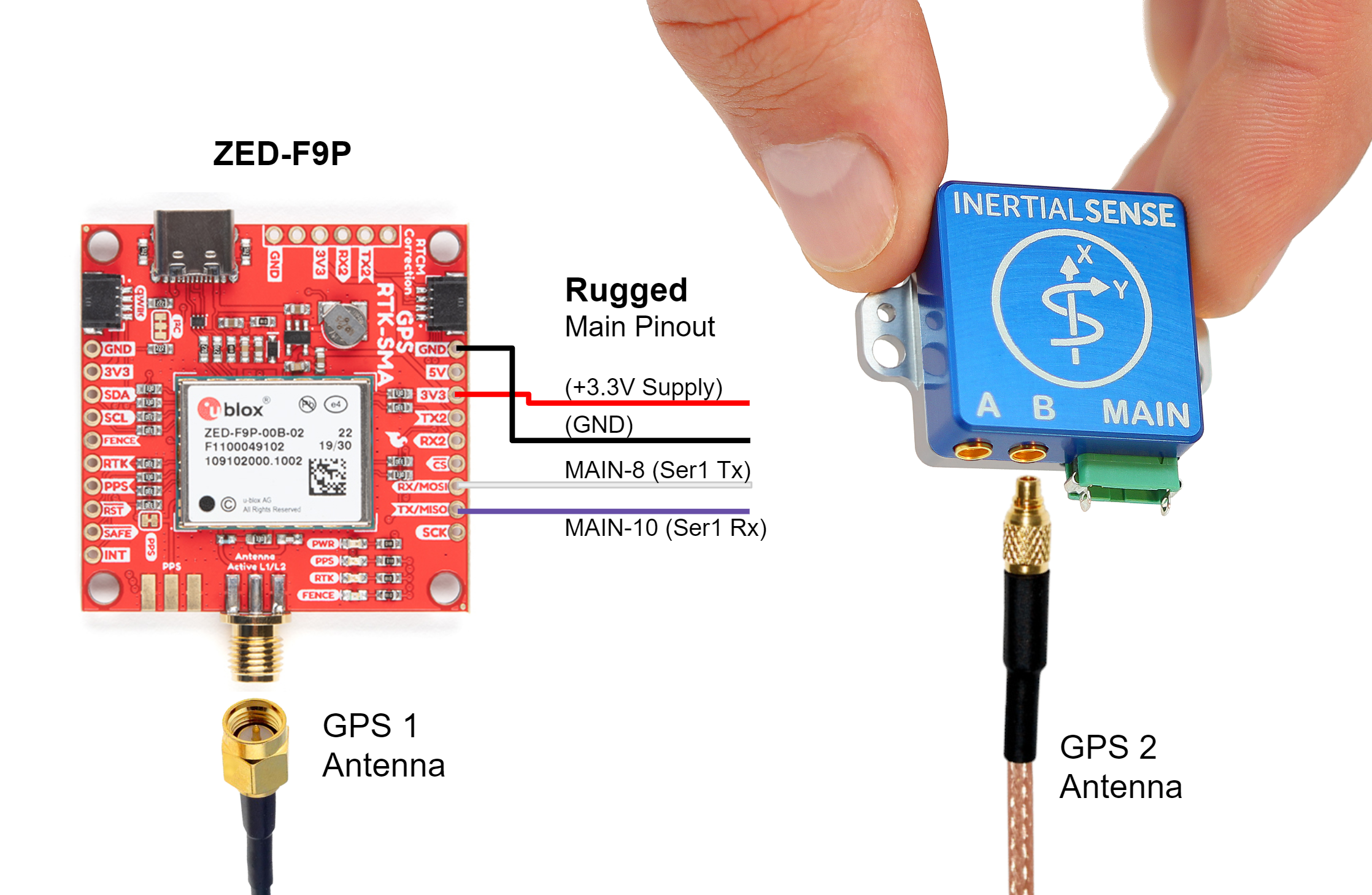 
A +3.3V or +5V supply is needed to power the ZED-F9P when using the Rugged-1 IMX. A USB +5V supply can be used if available. The Rugged-1 must be configured for Serial Port 1 TTL voltage. See hardware configuration for Rugged v1.0 or Rugged v1.1 for details.
Settings
See the single GNSS settings.
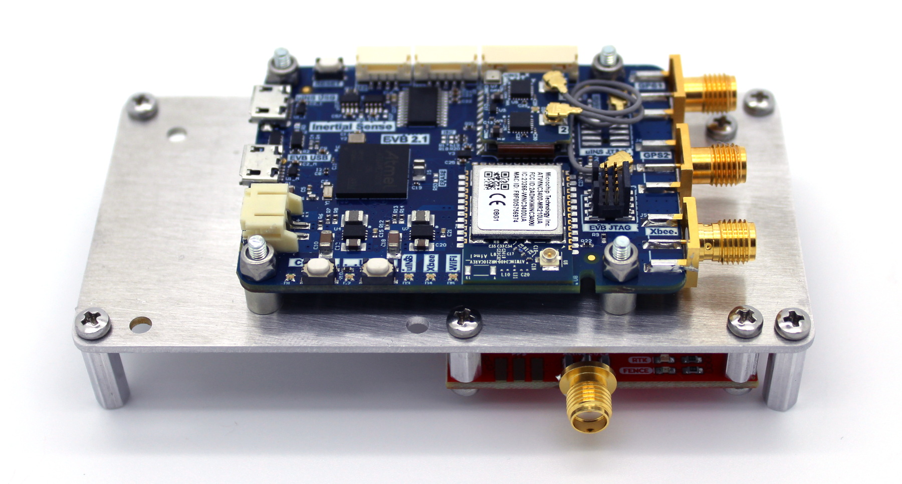
EVB-2 to Dual ZED-F9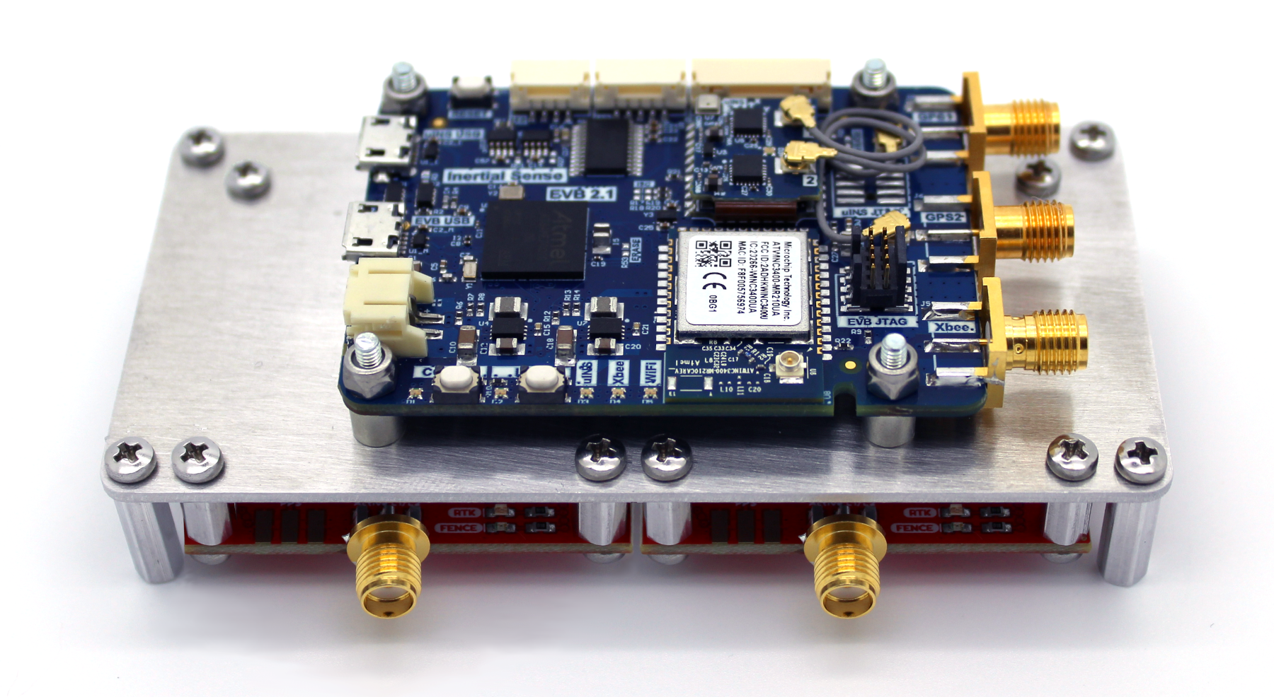 
Two ZED-F9 units can be used to provide either or both multi-band RTK compassing and RTK positioning for the INS solution. The ZED-F9Ps can be powered using the EVB-2 +3.3V output. Serial port 0 and 1 must both be used to communicate with the ZED-F9P.
Dual GNSS Pinout
| EVB-2 | IMX | GPS1 ZED-F9P |
|---|---|---|
| H7-1 |
GND | GND |
| H7-3 |
+3.3V | 3V3 |
| H7-11 |
Ser1 Tx | RxD |
| H7-10 |
Ser1 Rx | TxD |
| H7-12 |
G8 TIMEPULSE | PPS |
| EVB-2 | IMX | GPS2 ZED-F9P |
|---|---|---|
| H7-2 |
GND | GND |
| H7-3 |
+3.3V | 3V3 |
 H7-6 H7-6 |
Ser2 Tx* | RxD |
 H7-5 H7-5 |
Ser2 Rx* | TxD |
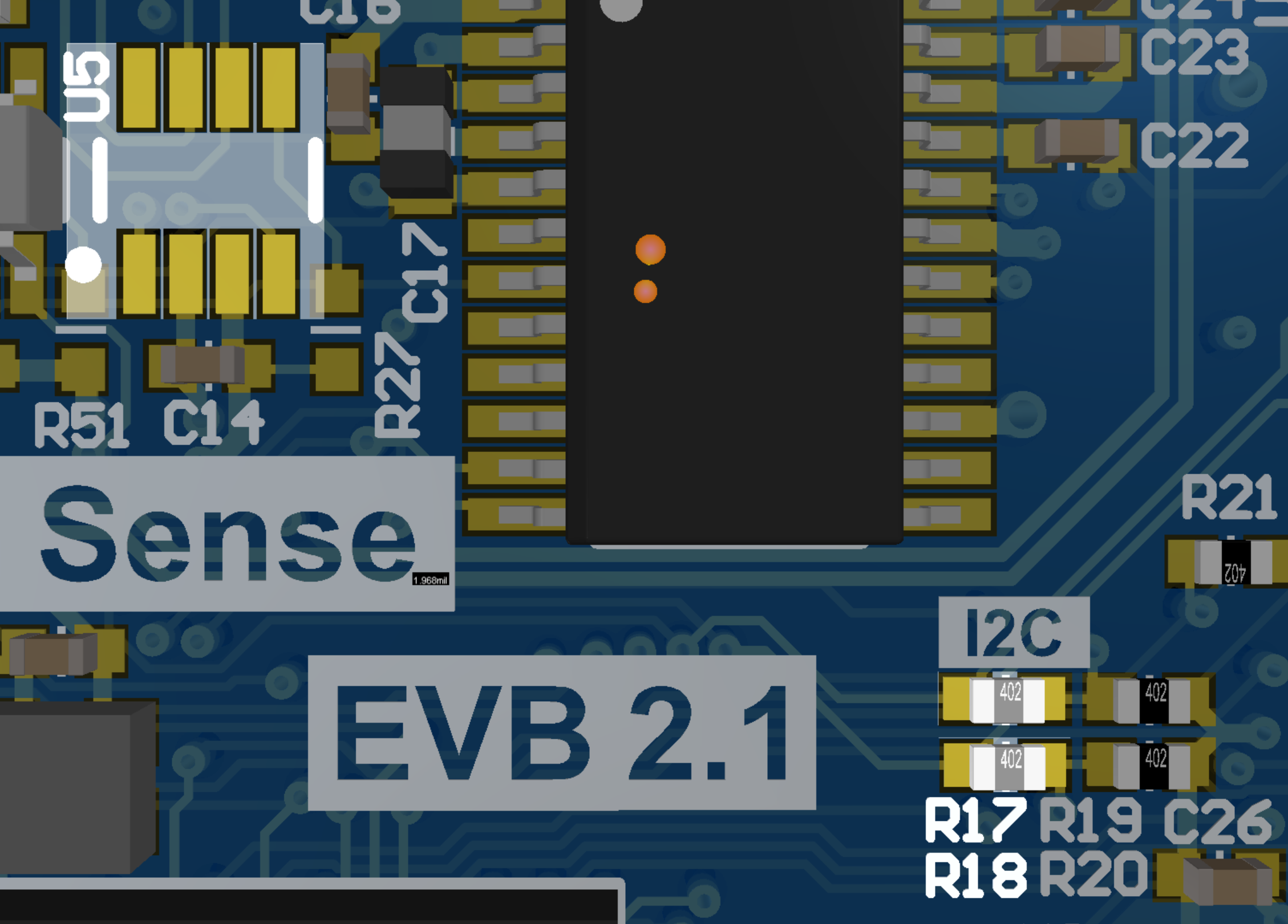
*R17 and R18 on the EVB-2 must be loaded with a zero ohm jumpers to connect Ser2 to H7 and U5 must be removed from the EVB-2.
Dual GNSS Settings
The following settings are used when two GPS receivers are connected to the IMX. These settings can be applied either using the EvalTool GPS Settings tab or the IMX DID_FLASH_CONFIG.ioConfig and DID_FLASH_CONFIG.RTKCfgBits fields.
GPS Ports
Set the serial port that the ZED-F9P is connected to and type to ublox F9P.
| DID_FLASH_CONFIG | Value |
|---|---|
| ioConfig (firmware >=1.8.5) | 0x026ca040 |
RTK Rover
Enable RTK rover mode by selecting Precision Position External. GPS1 is designated for Precision Position External and GPS2 for F9P Compass settings. Either or both can be enabled at the same time.
| DID_FLASH_CONFIG | Value |
|---|---|
| RTKCfgBits | 0x00000006 |
RTK Base
To configuring a system as an RTK base, skip the RTK rover settings, and select the appropriate correction output port on the IMX. Notice that IMX serial port 0 and 1 may be unavailable and occupied by the dual ZED-F9P receivers.
| DID_FLASH_CONFIG | Value |
|---|---|
| RTKCfgBits | 0x00000900 |
RTK Base Messages
In RTK mode, the ZED-F9P requires RTCM version 3 messages supporting DGNSS according to RTCM 10403.3.
ZED-F9 Rover Messages
The ZED-F9P operating in RTK rover mode can decode the following RTCM 3.3 messages.
| Message type | Description |
|---|---|
| RTCM 1001 | L1-only GPS RTK observables |
| RTCM 1002 | Extended L1-only GPS RTK observables |
| RTCM 1003 | L1/L2 GPS RTK observables |
| RTCM 1004 | Extended L1/L2 GPS RTK observables |
| RTCM 1005 | Stationary RTK reference station ARP |
| RTCM 1006 | Stationary RTK reference station ARP with antenna height |
| RTCM 1007 | Antenna descriptor |
| RTCM 1009 | L1-only GLONASS RTK observables |
| RTCM 1010 | Extended L1-only GLONASS RTK observables |
| RTCM 1011 | L1/L2 GLONASS RTK observables |
| RTCM 1012 | Extended L1/L2 GLONASS RTK observables |
| RTCM 1033 | Receiver and antenna description |
| RTCM 1074 | GPS MSM4 |
| RTCM 1075 | GPS MSM5 |
| RTCM 1077 | GPS MSM7 |
| RTCM 1084 | GLONASS MSM4 |
| RTCM 1085 | GLONASS MSM5 |
| RTCM 1087 | GLONASS MSM7 |
| RTCM 1094 | Galileo MSM4 |
| RTCM 1095 | Galileo MSM5 |
| RTCM 1097 | Galileo MSM7 |
| RTCM 1124 | BeiDou MSM4 |
| RTCM 1125 | BeiDou MSM5 |
| RTCM 1127 | BeiDou MSM7 |
| RTCM 1230 | GLONASS code-phase biases |
| RTCM 4072.0 | Reference station PVT (u-blox proprietary RTCM Message) |
ZED-F9 Base Output Messages
The ZED-F9P operating in RTK base mode will generate the following RTCM 3.3 output messages depending on whether the satellite constellation have been enabled. See the Constellation Selection for information on enabling and disabling satellite constellations.
| Message Type | Period (sec) | Description |
|---|---|---|
| RTCM 1005 | 2 | Stationary RTK reference station ARP |
| RTCM 1074 | 0.4 | GPS MSM4 |
| RTCM 1077 | 0.4 | GPS MSM7 |
| RTCM 1084 | 0.4 | GLONASS MSM4 |
| RTCM 1087 | 0.4 | GLONASS MSM7 |
| RTCM 1094 | 0.4 | Galileo MSM4 |
| RTCM 1097 | 0.4 | Galileo MSM7 |
| RTCM 1124 | 0.4 | BeiDou MSM4 |
| RTCM 1127 | 0.4 | BeiDou MSM7 |
| RTCM 1230 | 2 | GLONASS code-phase biases |
NTRIP Messages
The NTRIP server must provide the necessary subset of RTCM3 messages supported by the IMX-RTK. See the NTRIP page for an overview of NTRIP.
ZED-F9P Firmware Update
The following section describes how to view the current GPS firmware version and how to update the firmware on the uBlox ZED-F9P GNSS receiver through the IMX.
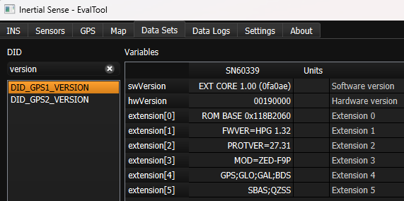
GPS Firmware Version
The current GPS firmware version can be read through the DID_GPS1_VERSION and DID_GPS2_VERSION messages.
Firmware Update
The following steps describe how to update the uBlox ZED-F9P firmware. The uBlox U-Center application software and firmware binary can be downloaded from the uBlox ZED-F9P documentation and resources webpage.
-
Enable IMX Serial Bypass - Send the system command (
DID_SYS_CMD)SYS_CMD_ENABLE_SERIAL_PORT_BRIDGE_USB_TO_GPS1orSYS_CMD_ENABLE_SERIAL_PORT_BRIDGE_USB_TO_GPS2to enable serial bypass on the IMX. This will create a direct connection between the current IMX serial port and the GPS. This is done in the EvalTool using the Factory Options dialog in the Settings -> General tab.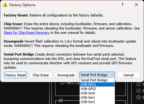
-
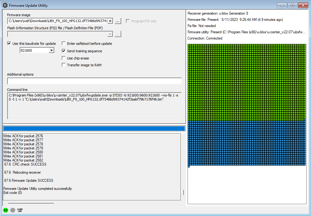
Update Using U-Center - With the IMX serial bypass enabled, the uBlox U-Center software can connect directly to the ZED-F9P GPS. Use the following steps in the ublox U-Center app:
- Open the serial port with baudrate 921600.
- Select Tool -> Firmware Update and specify the uBlox F9P firmware file (i.e.
UBX_F9_100_HPG132...bin).
- Enable "Use this baudrate for update" as 921600.
- Disable "Enter safeboot before update".
- Enable "Send training sequence".
-
Start the firmware update by pressing the small green "GO" circle in the bottom left corner of the Firmware Update Utility dialog.
- Power cycle the IMX.
Multi-Band GNSS Components
The following is a list of the ZED-F9P GNSS receivers and compatible antenna(s).
| Item | Supplier# | Description |
|---|---|---|
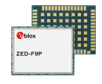 |
ZED-F9P-01B | ublox ZED-F9P high precision GNSS SMT module. GNSS bands: L2OF, L2C, E1B/C, B2I, E5b, L1C/A, L1OF, B1I. Concurrent GNSS: BeiDou, Galileo, GLONASS, GPS / QZSS. RTK 1cm horizontal accuracy. |
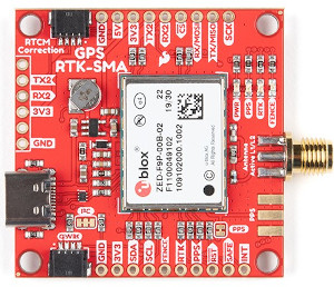 |
GPS-16481 | SparkFun GPS-RTK-SMA breakout board with ZED-F9P GNSS module. |
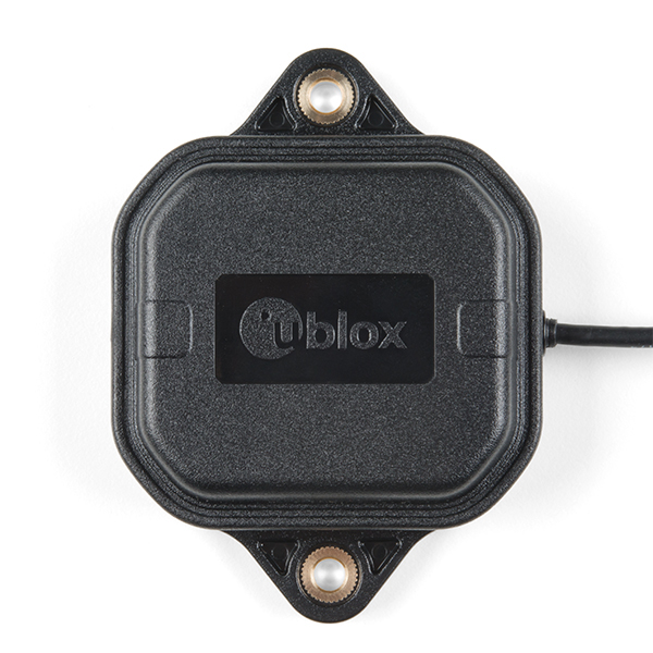 |
SparkFun: ANN-MB-00 ublox: ANN-MB-00 |
ublox Multi‑frequency GNSS antenna (L1, L2/E5b/B2I) active magnet mount. Supports GPS, GLONASS, Galileo, and BeiDou. 5m SMA cable. Designed for ZED-F9P. |
 |
AA.200.151111 | Taoglas multi‑band GNSS antenna (GPS/QZSS-L1/L2, GLONASS-G1/G2/G3, Galileo-E1/E5a, and BeiDou-B1/B2) active magnet mount. Supports GPS, GLONASS, Galileo, and BeiDou. 1.5m SMA cable. 63.2 x 67.2 mm. |
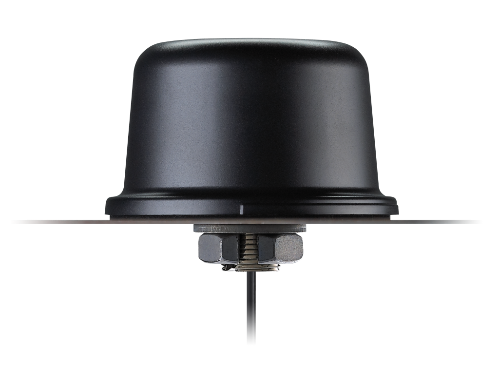 |
QHA.50.A.301111 | Taoglas multi-band GNSS antenna (GPS/QZSS-L1/L2, GPS/QZSS/IRNSS-L5, QZSS-L6, Galileo-E1/E5a/E5b/E6, GLONASS-G1/G2/G3, BeiDou-B1/B2a/B2b/B3). permanent mount. IP67 rated waterproof. 3m RG-174 SMA cable. 94mm (dia). |
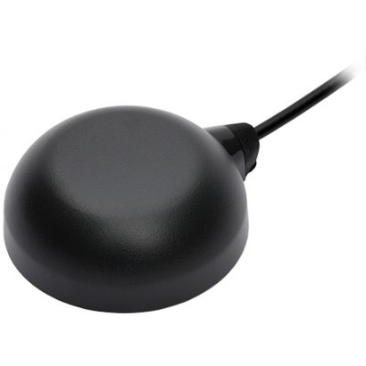 |
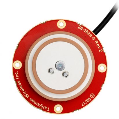
TW8889 | Tallysman multi‑band GNSS antenna (GPS/QZSS-L1/L2, GLONASS-G1/G2/G3, Galileo-E1/E5a, and BeiDou-B1/B2) active magnet mount. Supports GPS, GLONASS, Galileo, and BeiDou. 3m SMA cable. 47mm (dia), 52g. |
 |
TW7882 | Tallysman multi‑band GNSS antenna (GPS/QZSS-L1/L2, GLONASS-G1/G2/G3, Galileo-E1/E5a, and BeiDou-B1/B2) active magnet mount. Supports GPS, GLONASS, Galileo, and BeiDou. 3m SMA cable. 69mm (dia), 180g. |
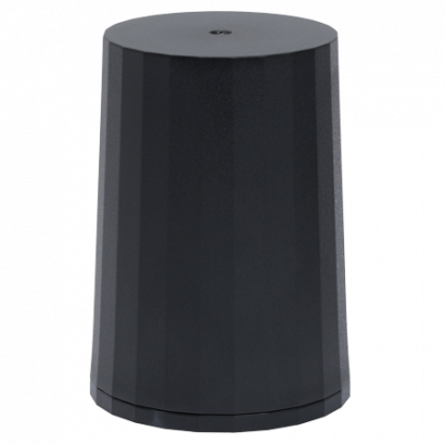 |
HC882 | Tallysman multi‑band helical GNSS antenna (GPS/QZSS-L1/L2, GLONASS-G1/G2/G3, Galileo-E1/E5a, and BeiDou-B1/B2) active magnet mount. Supports GPS, GLONASS, Galileo, and BeiDou. SMA. 44.2mm (dia), 42g. |
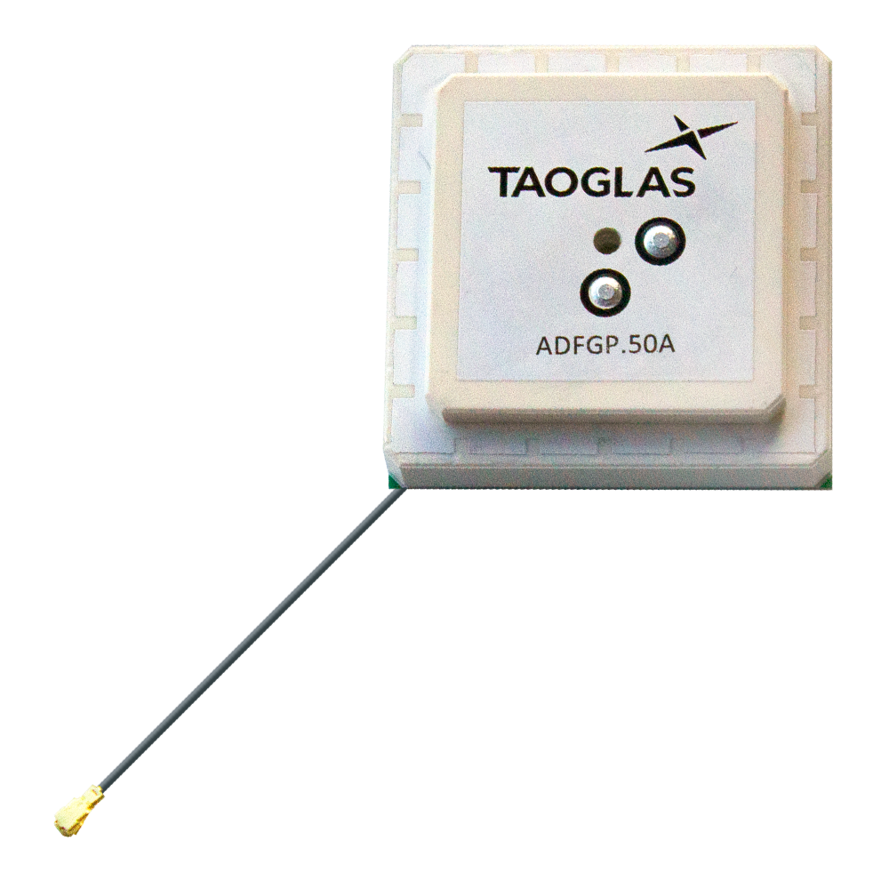 |
ADFGP.50A.07.0100C | Taoglas embedded multi-band GNSS antenna (GPS/QZSS L1/L2, GLONASS G1/G2/G3, Galileo E1/E5a/E5b, BeiDou B1/B2a/B2b). 50x50mm, 95.5g. |
 |
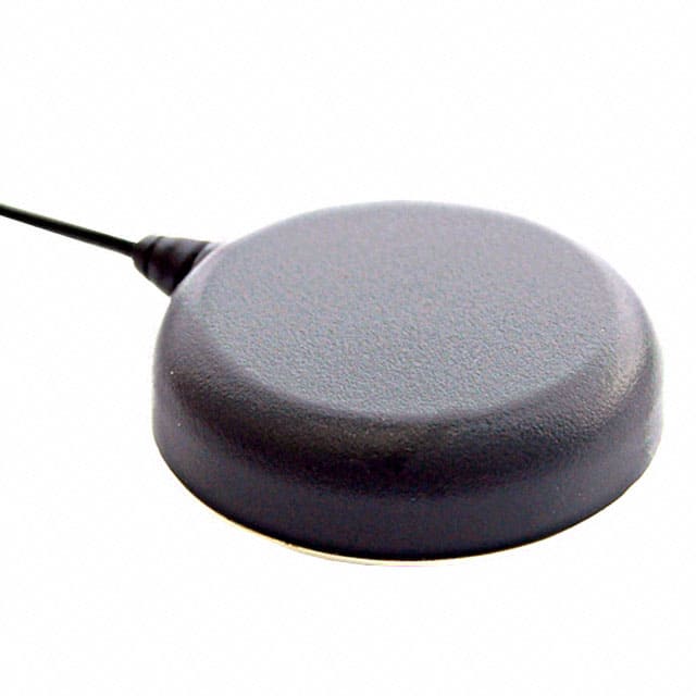
TW1889 | Tallysman embedded multi-band GNSS antenna (GPS/QZSS L1/L2, GLONASS G1/G2/G3, Galileo E1/E5b, BeiDou B1/B2). 48mm (dia), 37g. |
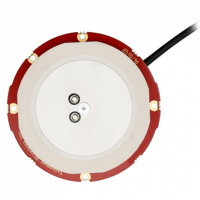 |
TW3887 | Tallysman multi-band GNSS antenna (GPS/QZSS-L1/L2, GLONASS-G1/G2/G3, Galileo-E1/E5a, and BeiDou-B1/B2). 60mm (dia), 70g. |